What's new

Simple VLAN across two switches not working as expected

  • SNBForums Code of Conduct

    SNBForums is a community for everyone, no matter what their level of experience.

    Please be tolerant and patient of others, especially newcomers. We are all here to share and learn!

    The rules are simple: Be patient, be nice, be helpful or be gone!

dfrac

New Around Here
Greeting everyone.

I'm trying to configure a small home network with VLAN spanning across two switches.

My setup is a much simpler version than the setup explained here: http://www.smallnetbuilder.com/lanw...segment-a-small-lan-using-tagged-vlans-part-2

This link is also quite relevant, http://www.eetimes.com/document.asp?doc_id=1272019 and this http://kb.netgear.com/app/answers/d...wo-netgear-switches-to-exchange-multiple-vlan

I have studied these, as well as the manuals and done a lot of trial and error. I feel I've reached the point where it seems fair to ask for advice from someone experienced. Any help would be appreciated.

This is purely a layer 2/VLAN problem. The computers involved all have static IP addresses and can communicate perfectly fine when the VLAN settings are disabled.


The setup:

Switch 1 is a Cisco 200-08.
Switch 2 is a Zyxel GS1900.

I have the standard VLAN 1 and I have defined my own VLAN 2.

The switches are connected together like this: Switch 1 is connected by port 4 to switch 2. Switch 2 is connected to switch 1 also by port 4.

Switch 1 has a computer A connected on port 1.
Switch 1 has a computer B connected on port 2.

Switch 2 has a computer C connected on port 2.
Switch 2 has a computer D connected on port 3.


Computer A and D should be on VLAN 2.
Computer B and C should be on VLAN 1.


What I want:

Computer B, being on VLAN 1, should not be able to reach computer D on VLAN 2.
Computer A, being on VLAN 2 should be able to reach computer C, as they are both on the same VLAN (2).

I can get this to work on the same switch, but the moment I try to "propagate" the VLAN across the switches, nothing makes sense any longer.


My question:

* Is this even possible given the switches that I have? They should both support 802.1q.

* What is the correct configuration to make this work?


What I've tried:

I've followed this exact setup:

http://kb.netgear.com/app/answers/d...wo-netgear-switches-to-exchange-multiple-vlan

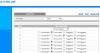
Configuration for computer A and D:

Membership: VLAN 2
PVID: 2
Tagging: Untagged

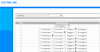
Configuration for switch A and B port 4 (port 4 is the port used to connect them):

Membership: VLAN 1 and 2.
PVID: Not relevant, set to 1.
Tagging: VLAN 1 tagged, VLAN 2 tagged.

This results in computer A not being able to reach computer D at all.

I've tried a lot of different configurations, either I cannot reach D or everyone can reach D.

My test setup is basically just running ping continuously from computer A and B to see who can talk to who while I try different setups.
 
Last edited:
The way I like to handle VLANs is to tag them with 802.1Q. To connect 2 switches with VLANs and have the VLANs flow through both switches I like to create a trunk port on each switch to connect them with both tagged VLANs on both switches. This allows all the VLANs to flow on both switches but I define each VLAN as a separate network so neither VLAN can access each other. I then turn on routing on a router or layer 3 switch for the VLANs. This allows the VLANs to access each other. I then setup ACLs, access control lists, to regulate which devices can talk to each other. This process works very well in small and large networks.

Using ACLs will allow you to control down to the port level not just an IP address.
 
Last edited:
The way I like to handle VLANs is to tag them with 802.1Q. To connect 2 switches with VLANs and have the VLANs flow through both switches I like to create a trunk port on each switch to connect them with both tagged VLANs on both switches. This allows all the VLANs to flow on both switches but I define each VLAN as a separate network so neither VLAN can access each other. I then turn on routing on a router or layer 3 switch for the VLANs. This allows the VLANs to access each other. I then setup ACLs, access control lists, to regulate which devices can talk to each other. This process works very well in small and large networks.

Thanks for the input.

I should point out that I don't intend to use any layer 3 functionality.

I have port 4 defined as a trunk port on both switches, and this port (same on both) is what connects the two switches together.

On the Cisco switch I can specify "Operational VLAN membership". I have this defined for port 4 to be both VLAN ID 1 (untagged) and 2 (tagged). I also have port 1 as member of VLAN ID 2.
On the Zyxel I have port 3 and 4 tagged for VLAN ID 2, untagged for VLAN ID 1 on port 4.

Shouldn't this be enough for computer A to reach computer C? They are both on VLAN 2, and the switches appear to be connected correctly by the trunk port 4.

Are there any obvious mistakes with this?
 
This will work.
You just need to set the "uplink" correctly
For simple home use.
On both switches do the following to the ports joining the switches:
On the uplink set the PVID to 1
Set the Untagged VLAN to 1
Tag VLAN 2
Tag additional VLANs as required.

Testing should be done internally on the switch first followed by over the link.

Eg. for computer A and D make sure they can talk properly on the cisco without talking to computer B.

I'm assuming you mean I should tag the uplink port for VLAN 2, but not the access ports used to connect the computers?

I've tried this.

This is all for tagging VLAN 2:

If port 3 and 4 on switch 2 are both untagged then computer A can ping D.
If port 3 and 4 on switch 2 are both tagged then computer A can not ping D.
If (on switch 2) port 3 is tagged and port 4 is not tagged, then computer A can ping D.
If (on switch 2) port 3 is not tagged and port 4 is tagged, then computer A can not ping D.

Edit: I forgot to add that if I exclude port 3 on switch 2 from VLAN 1, then no combination of these parameters work. As if the tag doesn't get forwarded from switch 1 to switch 2 at all.

Is it possible that the Zyxel switch doesn't support what I'm trying to do?
 
Last edited:
The zyxel will do it.
You want the computers on access ports, not trunk ports. Only connect switch to switch by trunk ports.

If you want a machine on VLAN 2 the pvid and untagged Id should be 2.
 
Hi, I want to revive this thread. I am having the exact same problem. No matter what I have tried, I am not able to get this working.

My scenario is that I have an Lte-router in the garage because I get best coverage there. This router is in bridge mode, and it is not vlan capable, thus not possible to use the other three ports on it for a LAN in the garage.

The other router with my firewall is in my house and I have one cat6 cable between the two buildings.

Now, I have a Zyxel GS1900-24E in the house, and a zyxel GS1200-8HP in the garage. I am actually not sure now if the 1200 supports this configuration.

The goal is to use the single CAT6 cable to create a link between the two switches. Then let the traffic from the LTE-router pass on VLAN 100 and all the other traffic on VLAN1. I have tried every possible config of untagged and tagged and pvids. I get it to work sometimes but only in one direction. It is not posible to make the traffic flow both ways.

This should be the most basic and simple task one should try to configure with VLANs but no. Two VLANs on the "trunked" ports on the two switches. A single VLAN on a separate port on each switch. That should do it?

Is there anyone that can help me out here with the exact configuration needed for this to work?
 
Hi, I want to revive this thread. I am having the exact same problem. No matter what I have tried, I am not able to get this working.

Ok create your 802.1q VLANs on each switch (VLAN100 and VLAN1 - I assume VLAN1 is already there and is the default). Ok so lets say port 1 on each switch is the port you are using to connect the two. So port1 would be tagged in both VLAN1 and VLAN100 (on both switches) and go ahead and make the PVID for those ports VLAN100 (the PVID on a tagged port really does not matter but I digress). Ok so lets plug your LTE router in to port2 on its switch and your other router's WAN port into port2 on its switch. So now on both switches configure port2 to be untagged in VLAN100 with a PVID of 100. Now all your other ports on the switches can be configured as untagged in VLAN1 with a PVID of 1. No ports besides port 1 should be a member of more than one VLAN. Finally plug one of your LAN ports on your router (not your LTE router but the other one) into an open port on its switch (which should be in VLAN1).

Some switches are pretty liberal on how they will let you set a port. This can make a mess if your not careful. I don't know about your switches but make sure the ports that are tagged are only tagged and not tagged and untagged. The reverse is true for the untagged ports. In short make sure none of your ports are both tagged and untagged.
 
The way I would do it is to use tagged VLANs. I would create a trunk port between switches which means creating a trunk port on each switch and connecting them with your CAT6. The trunked port will carry all VLANs between switches. I use Cisco and that is what I know.
 
Thank you abailey. I have configured like you said, but what happens is that my asus firewall router detects a ipconflict. first of all, my WAN subnet is at 192.168.0, and my LAN subnet is at 192.168.1, both with 3x255.0. So it is very strange that they should somehow be on the same subnet.

However, when I go to "system information" I can see something that strikes me as odd.
There are one device that is "present" at both wan and lan, like the firewall cant manage to separate its wan and lan port, and the device last seen is one that is clearly on the LAN. Look at the pics direct from LTE and VLAN100

I can also see that in the Asus WAN is configured as vlan 2, but I have no idea where this is configured, I have looked everywhere. I am not sure if it will help to put 100 there. 2 is different from 1 anyway. and traffic from vlan1 is getting over to the wan port somehow.

syslog of the asus
Feb 19 20:40:36 WAN Connection: The LAN's subnet may be the same with the WAN's subnet.
 

Attachments

  • House switch vlan1 config.PNG
    House switch vlan1 config.PNG
    148.7 KB · Views: 545
  • house switch vlan 100 config.PNG
    house switch vlan 100 config.PNG
    157.1 KB · Views: 773
  • garage switch vlan config.PNG
    garage switch vlan config.PNG
    218.1 KB · Views: 666
  • wan direct from LTE.PNG
    wan direct from LTE.PNG
    89.8 KB · Views: 450
  • wan from vlan100.PNG
    wan from vlan100.PNG
    74.5 KB · Views: 474
Ok so you have Port 2 on the home switch attached to Port 8 in the Garage right? You have the WAN port of the ASUS attached to Port 3 of the home switch right? You have the LTE router attached to Port 7 in the garage right? If so, can you post the PVID sceens for the two switches?

Also which port on the Home switch do you have the Asus Lan attached to?
 
Your last post made me check everything once again, and stupid me had managed to put the WAN port of the ASUS in port 4, not port 3. By correcting this the wan traffic worked as expected. I didnt check if the lan is present on ports 1-6 in the garage, but I will do this tonight.

So to your questions, the answer is yes, no, yes on the first three, where it should have been yes,yes,yes.
I didnt have the time to take a picture of the pvid config of the house switch, but it is 100 on both port 2 and 3. The garage switch is 100 on ports 7 and 8, as can be seen in the pic I provided in my last post.

When I look at the config now it all makes perfectly sense. I am wonderinng though, why we set the pvid to 100 on both of the ports in question on both switches? Is there a reason why we dont set pvid to 1 on the "backbone"?
 
When I look at the config now it all makes perfectly sense. I am wonderinng though, why we set the pvid to 100 on both of the ports in question on both switches? Is there a reason why we dont set pvid to 1 on the "backbone"?

You certainly can set the PVID to 1 on the backbone if you want to. In your configuration the PVID of the backbone should not matter. Personally I don't like using the default VLAN for anything. I usually make a new VLAN to replace the default and I make a separate VLAN just for "backbone" ports and set their PVID to that VLAN. But that is just personal preference. So to answer your question, I said put the "backbone" on 100 to keep it away from the default VLAN1.
 
Similar threads
Thread starter Title Forum Replies Date
D VLAN Config Query using pfSense and Unifi Switches, NICs and cabling 18

Similar threads

Latest threads

Sign Up For SNBForums Daily Digest

Get an update of what's new every day delivered to your mailbox. Sign up here!
Top