What's new

How to debrick Asus RT-N66U with OpenOCD ?

  • SNBForums Code of Conduct

    SNBForums is a community for everyone, no matter what their level of experience.

    Please be tolerant and patient of others, especially newcomers. We are all here to share and learn!

    The rules are simple: Be patient, be nice, be helpful or be gone!

jimtale

Occasional Visitor
Hello all,

I happened to have a bricked Asus RT-N66U with 3 LEDS on. My goal is to erase and flash CFE so hopefully it can boot again,
Here are my procedures:

Bought TUMPA JTAG usb thingy, connected TUMPA's JTAG to J1 of Asus, TUMPA TTL COM to J2 of Asus,
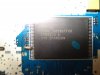
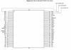
I soldered 4.99K to pin 21 of Flash IC, downloaded OpenOCD 0.8,
Replace/Copy files from http://openocd.zylin.com/#/c/2153/
to corresponding directories,

When I run these commands, I got the following results:
Code:
ocd -f C:\Users\protos\Deskto
p\Asus\openocd-0.8.0\scripts\interface\ftdi\tumpa.cfg -f C:\Users\protos\Desktop
\Asus\openocd-0.8.0\scripts\tools\firmware-recovery.tcl -c "board asus-rt-n66u;
erase_part nvram; flash_part CFE CFE.bin; shutdown"
Open On-Chip Debugger 0.8.0 (2014-04-28-08:42)
Licensed under GNU GPL v2
For bug reports, read
        http://openocd.sourceforge.net/doc/doxygen/bugs.html
Info : only one transport option; autoselect 'jtag'
none separate


Firmware recovery helpers
Use -c firmware_help to get help

adapter speed: 1000 kHz

ATTENTION: you need to solder a 4.7-10k pullup resistor to pin 21 of flash IC
to enable JTAG, see http://wl500g.info/album.php?albumid=28&attachmentid=8991 ,
there is an unpopulated footprint near U8.

Info : clock speed 1000 kHz
Info : JTAG tap: bcm4706.cpu tap/device found: 0x1008c17f (mfg: 0x0bf, part: 0x0
08c, ver: 0x1)
Info : JTAG tap: bcm4706.cpu tap/device found: 0x1008c17f (mfg: 0x0bf, part: 0x0
08c, ver: 0x1)
target state: halted
target halted in MIPS32 mode due to debug-request, pc: 0x00000000
Error: auto_probe failed
Runtime Error: C:\Users\protos\Desktop\Asus\openocd-0.8.0\scripts\tools\firmware
-recovery.tcl:94:
in procedure 'erase_part'
in procedure 'flash' called at file "C:\Users\protos\Desktop\Asus\openocd-0.8.0\
scripts\tools\firmware-recovery.tcl", line 94

and...

Code:
log is too long, please see attached !

well, I thought it got stuck but no, google says if I open Telnet connection to port 4444, it worked !
but commands like erase_flash failed since it said it couldn't recognize the command.

Can anyone please give some instructions ?
 

Attachments

  • logocd.txt
    23 KB · Views: 753
  • logocd.txt
    23 KB · Views: 371
I happened to have a bricked Asus RT-N66U with 3 LEDS on. My goal is to erase and flash CFE so hopefully it can boot again,
Hi,

Are you sure that CFE is bad? If it's still OK you can use this to restore the firmware:
Briked ASUS routers can be flashed with firmware via the Firmware Restauration Tool (from the ASUS homepage in the support section of the router)... :rolleyes:

With kind regards
Joe :cool:
 
Hi,

Are you sure that CFE is bad? If it's still OK you can use this to restore the firmware:
Briked ASUS routers can be flashed with firmware via the Firmware Restauration Tool (from the ASUS homepage in the support section of the router)... :rolleyes:

With kind regards
Joe :cool:

Hey Joe,
I am sure the CFE is bad hence the efforts. As of now, its just 3 solid lights instantly when powered up. No ethernet activity so Asus tool is no use in this case.
With zJtag, and correct command like:
zjtag -probeonly /l1:3 /isntrlen:27 /noreset, I can get some other lights flashed, but no pings.

So far, I can mostly identified the CPU with Jtag, but no luck in recognizing the flash which is so hard.

I heard people succeeded with OCD so I was wondering if someone could help me...
 
What commands are you are using when accessing CPU? Are you able to init?

erase_part CFE not nvram

From what im seeing you are almost done, you only need to erase flash and write the file.

You should use this:

erase_part CFE; flash_part CFE /pathtoCFEbackupfile; shutdown
 
Last edited:
Hello hggomes,
Thanks for stopping by, I read many of your posts from this thread. :)

So, yes init command was ok but erase_part CFE returned invalid command, here is the log:
 

Attachments

  • telnet OCD.txt
    22 KB · Views: 588
It seems there was some changes on openocd, just use this option:

flash write_image [erase] [unlock] filename [offset [file_type]]
Write an image to flash. Optionally first unprotect and/or erase
the region to be used. Allow optional offset from beginning of
bank (defaults to zero)
 
I got the following errors running these commands, it seems the flash is not responding, or I haven't initialized it correctly.

Any suggestions !

Code:
init
> flash info
  flash info bank_id
in procedure 'flash'
> flash info 0
Target not halted
auto_probe failed
in procedure 'flash'
> flash erase_address 0xbc000000 0x00040000
Target not halted
auto_probe failed
in procedure 'flash'
> flash write_image erase CFE.bin 0xbc000000 bin
auto erase enabled
Target not halted
auto_probe failed
in procedure 'flash'
Error writing unexpected address 0xffffffff
target state: halted
target halted in MIPS32 mode due to undefined, pc: 0x00000000
> flash write_image erase CFE.bin 0xbc000000 bin
auto erase enabled
auto_probe failed
in procedure 'flash'
> flash write_image erase CFE.bin 0xbc000000 bin
auto erase enabled
auto_probe failed
in procedure 'flash'
 
The resistor is not in place, you should take a look at it, try a 10K resistor.
 
Ok, I will have to find a resistor tomorrow, I guess 4.99K didn't cut it, I will report back, thanks !
 
Please take a picture first of your flash/resistor.
 
Please take a picture first of your flash/resistor.
Here we go, my soldering skill is not something I am particularly proud of , lol.

But hey I checked, no shorting betwen pins, connections are perfect !
 

Attachments

  • DSC05550.JPG
    DSC05550.JPG
    57.9 KB · Views: 1,244
Is that a joke? You just soldered the the wrong resistor to pin 21 on the FLASH, thats not what you have to do.

Cannot understand where you got that information.
 
Last edited:
You should not solder anything to the flash pins, but to the missing footprint 2 points.

Take a look at those 2 pictures:

http://imgur.com/RGp0NAn,Uox4JPF

Please make sure you dont do that kind of errors again or you risk killing the FLASH.
 
Last edited:
I understand, but I don't have the tiny resistors, only the standard size. Electrically it is the same, pin 21 to Vcc, the other 3 pins on the same row are:
Pin 19 (A17) → VCC
Pin 16(WP) → VCC
Pin 17(RY) → VCC

Pin 21 is A6, I am not sure why it should be pulled up, but it is pulled up now.
 

Attachments

  • Clipboard_20150316.png
    Clipboard_20150316.png
    164.3 KB · Views: 686
You can remove it from an old board or other device, that was what i have done, and TBH i dont think it will work that way.

I have a friend that was also working around it because he also had the same problem and that trashed the FLASH, thats all im saying here. :)

Im sure you will find one small resistor and you will be able to solder it easily.

Good luck, if you need anything else after just ask :)
 
Last edited:

Similar threads

Latest threads

Sign Up For SNBForums Daily Digest

Get an update of what's new every day delivered to your mailbox. Sign up here!
Top