What's new

Will MoCA Work?

  • SNBForums Code of Conduct

    SNBForums is a community for everyone, no matter what their level of experience.

    Please be tolerant and patient of others, especially newcomers. We are all here to share and learn!

    The rules are simple: Be patient, be nice, be helpful or be gone!

Still wondering about the 2nd "street" line(s)... Any chance these two cables are opposite ends of the same cable? Or does the “Basement” street line pass through the entry point? (Seems odd that it would be a street line with a wholly separate path to the pole.)
The basement street line does not pass by the entry point… it goes out a window and along the side of the house so it probably is the same line as the one I have disconnected at the entry point that I thought was coming from the street. I will check soon and find out.

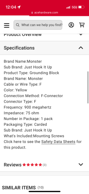
I will try the 3ghz barrel connector asap. I already tried this but with a 1ghz barrel connector and it did not work… I have an order of 3ghz barrel connectors coming on Monday, I’ll try then.
 
The basement street line
What I've been wondering is whether shifting the entry point and "PoE" MoCA filter might improve the path loss and MoCA connectivity to the "left side" endpoints. (Additional loss savings could be achieved by right-sizing splitters to just the number of outputs actually needed.)

Worst case, this shift improves the logistics of using one of the "Corner Case" topologies from the Best Practices doc, as well as employing a MoCA-optimized amplifier in place of the "Basement" 4-way splitter, if needed, as the "Basement" splitter is now the top-level/drop location.

Example diagram:

Corrected w alternate street line.png
 
Last edited:
Ok I’ll give that shot but how do I get the cable tv signal to go thru? I honestly only need it in the family room.
If this is in reference to the last diagram, with the shifted pole entry line, I'm not sure that I understand. The diagram *is* dependent on the coax line feeding the "Basement" splitter input port coming from the street/pole, and it carrying the needed QAM TV signal.
 
If this is in reference to the last diagram, with the shifted pole entry line, I'm not sure that I understand. The diagram *is* dependent on the coax line feeding the "Basement" splitter input port coming from the street/pole, and it carrying the needed QAM TV signal.
Ok I’ll have to check if it is coming from the pole or if it really is that the other end is by the original point of entry box.
 
Ok I’ll have to check if it is coming from the pole or if it really is that the other end is by the original point of entry box.
Either way would work, right? If it is the same line by the original point-of-entry, it's then a second dual coax line I was hoping for earlier right, running from the original point-of-entry to the basement splitter? You'd then have the two parallel lines necessary to extend the incoming provider coax from that point-of-entry directly to the basement splitter input, and then the second line to route back up to/through that junction box enroute to the "left side" splitter.

Corrected main PoE extended.png
 
and if you join those two coax cables out at the demarc box, do so with an earthing union block and properly connect it earth the same way the existing ISP coax is.
 
Either way would work, right? If it is the same line by the original point-of-entry, it's then a second dual coax line I was hoping for earlier right, running from the original point-of-entry to the basement splitter? You'd then have the two parallel lines necessary to extend the incoming provider coax from that point-of-entry directly to the basement splitter input, and then the second line to route back up to/through that junction box enroute to the "left side" splitter.

View attachment 53935
So when I started taking things apart and figuring out what goes where This is what the demarc/entry point looked like
 
Either way would work, right? If it is the same line by the original point-of-entry, it's then a second dual coax line I was hoping for earlier right, running from the original point-of-entry to the basement splitter? You'd then have the two parallel lines necessary to extend the incoming provider coax from that point-of-entry directly to the basement splitter input, and then the second line to route back up to/through that junction box enroute to the "left side" splitter.

View attachment 53935
Ok I did as you said but it did not work until i removed the moca adapter coax cable from basement splitter connected it to a coupler that then connects to the coax cable that goes to entry point (which as you instructed is connected to a coupler going to the roof). Then on the left side of the house on the 2nd floor I directly connected the coax from entry point to the one leading to the carriage house.
 
Ok I did as you said but it did not work until i removed the moca adapter coax cable from basement splitter connected it to a coupler that then connects to the coax cable that goes to entry point
Not sure what this means. Do you mean to say that the Carriage House only connected when the coax line running to the “primary MoCA adapter” bypassed the “Basement” splitter and was effectively run directly to the Carriage House? (Losing all other MoCA connectivity, and cutting the Carriage House off from the cable signal?)

Was the “left side” splitter bypassed, as well?
 
So when I started taking things apart and figuring out what goes where This is what the demarc/entry point looked like
Depending on which lines are connected where, that looks like the “after” for the suggested promotion of the “basement” splitter as the initial splitter. Or was that how you found it, the “before”?

(Ideally the pictured ground blocks would be rated to 3 GHz; not likely an issue but something to keep in mind.)
Everything seems to be working fine now except for cable tv but that’s okay because we’re using Apple TVs now and accessing the spectrum tv channels thru it. Attached are images of the Carriage house moca.. does that look good?
 

Attachments

  • IMG_9271.png
    IMG_9271.png
    51.4 KB · Views: 21
  • IMG_9272.png
    IMG_9272.png
    62.9 KB · Views: 15
3 GHz would be preferable (example), especially where MoCA is at its limits.

The current ground block isn’t a filter, so it’s not like you know MoCA signals are being stepped on; but performance at MoCA frequencies is undetermined, at best, not what you want.
Thank you! Could you tell me if these signals look fine
 

Attachments

  • IMG_9271.png
    IMG_9271.png
    51.4 KB · Views: 23
  • IMG_9272.png
    IMG_9272.png
    62.9 KB · Views: 28
Depending on which lines are connected where, that looks like the “after” for the suggested promotion of the “basement” splitter as the initial splitter. Or was that how you found it, the “before”?

(Ideally the pictured ground blocks would be rated to 3 GHz; not likely an issue but something to keep in mind.)
That was the before and now it’s the after aswell
 
Everything seems to be working fine now except for cable tv but that’s okay because we’re using Apple TVs now and accessing the spectrum tv channels thru it. Attached are images of the Carriage house moca.. does that look good?

IMAGE 1: PHY rates
IMAGE2: Device Status
If that's MoCA 2.5, they're pretty awful, and somewhat surprising for there to be a connection. The node-to-node rates should ideally be at or just over 3500 Mbps for a 5-channel connection. (5x 700 Mbps).
 

Latest threads

Sign Up For SNBForums Daily Digest

Get an update of what's new every day delivered to your mailbox. Sign up here!
Top