What's new

How We Test Wireless Products - Revison 7

  • SNBForums Code of Conduct

    SNBForums is a community for everyone, no matter what their level of experience.

    Please be tolerant and patient of others, especially newcomers. We are all here to share and learn!

    The rules are simple: Be patient, be nice, be helpful or be gone!

bonsai

Occasional Visitor
This is my first posting here :)

First of all, i would like to thank you for this great Smallnetbuilder page, which already helped me several times to select "the good ones" out of the product Jungle.

The "kick" to register to this forum was this article:

http://www.smallnetbuilder.com/wireless/wireless-howto/32082-how-we-test-wireless-products-revison-7

...because some years ago I experimented with a similar setup, using radiation inside a box in combination with artificial pathloss by variable attenuators.

First with 11a/g products, where the method worked "reasonable" and later with 11N products where i faced some pitfalls, which made it difficult to achieve really comparable "range performance" results between different MIMO products.

The major problem for MIMO products is to make the air loss between ALL Router antennas and their chamber counter part antennas "comparable" for all different sorts of router and their different antenna designs.
In small chambers at short distances, a few inches difference in the distance between 2 antennas can already result in several dB difference in attenuation.

Some routers have external rubber stick antennas, others have integral antennas glued inside the housing and others even have the antennas directly printed on the PCB.

Not all routers use vertical antenna polarization, but some use horizontal or even mixed horizontal + vertical polarization....
Often it's difficult to conclude from the optical antenna appearance to it's polarization and radiation pattern.

In a real domestic (reflective) environment and at a certain distance, the signal reflections and diffractions (which are necessaray to make MIMO working) will equalize the differences in antenna polarization and directivity.

But in an anechoic line of sight scenario, the range-vs-rate performance will depend on how well the chamber antenna setup "matches" the router antenna setup.

A wrong polarization can easily add 10dB to the air loss.
A router antenna "1" can have a "gain-null" in the direction where antenna "2" has the maximum gain and MIMO performance will suffer from this attenuation inbalance.

It could be, that specific Routers radiate with one antenna to the front, one antenna to the right and a third antenna to the left, which is not a problem in an reflective domestic environment, but of disadvantage in an anechoic line of sight scenario, where the chamber antennas have significant less air loss to one of the antennas, than to the remaining MIMO antennas.

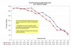
Any inbalance in air loss between the router antennas and chamber antennas lets the MIMO throughput degrade earlier, than if the all antennas have a very "balanced" view, like if testing the RT-AC66U, which's antenna setup fits optimally to the chamber antenna setup => 3* vertical against 3 * vertical and all antennas have exactly same distance to the counter part.

To be honest, i found no universal "one fits all" solution for a suitable MIMO chamber antenna setup.

One point of improvement could be placing the chamber antennas not close together, but in a large circle around the router under test, while putting the router in the center.
Another to turn all chamber Antennas in diagonal 45° position,which better enables picking up horizontal and vertical fields. Better would be switching to circular polarized wideband antennas, like Archimedian spiral type, but unfortunately these are quite expensive.


Bonsai
 
It is nice that you notice the flaws of the current way of testing wireless on most/all sites.
I think there is no 100% fair way to test wifi products.
Maybe manufacturers should mention the type and radiation pattern of the antennas that are used. Then customers could make a better decision about the wifi device that fits the job best.
 
Thanks for sharing your thoughts and testing knowledge @Bonsai, and welcome to the forums! ;)

One of the reasons I value the reviews on SNB as much as I do is because all of the complete router reviews analyze a physical dissection, bench testing, and real world LAN & WLAN performance

Like in car reviews - engine bench dyno tests of HP & torque are good to know, as is the diameter of the brake discs and how many pistons each caliper has... But repeatable 0-60, 60-0, and skid pad tests are what matters most.

And there was another good comment about routers potentially publishing their polarization pattern...on this PDF I linked to in another post earlier today they give you the plots on both axis of how this particular antenna radiates:

http://bit.ly/15DRGtS

Which is great when you're looking at single antennas, but probably far less useful when analyzing multiple stream radios that utilize beam reflection and some pretty complex concepts beyond traditional RF propagation.

I don't know how to measure the success or failure of the complex multi stream designs with anything other than actual file transfer speed, and not just connection strength in RSSI or link speed rate.

Edit: I'm aware that antenna radiation plot I linked to is actually depicting an array, but that still doesn't help us know exactly how the array will perform under 802.11n & AC.
 
Last edited:
Thanks for sharing your insights, Bonsai.

I'm the first to admit that SNB's wireless test process isn't perfect. I had many reservations when switching to it. But with the explosion of wireless modes to test and the steady march of new products, it was clear that the old walk-it-around process was unsustainable.

Yes, the process has the weaknesses that you point out and could be improved. But the data that goes into the posted results is much more extensive than the eight data points per band of the old process. The test process is consistently applied to provide as much of a controlled, relative comparison as reasonably possible.
 
Thanks for the many answers.
I can fully understand the effort to reduce the test times by automation.
Just want to make aware, that a "fair" test might require different chamber antenna setups, which individually depend on the antenna configuration of the router under test.

When looking at the Linksys EA6500 wireless re-test ...

http://www.smallnetbuilder.com/wireless/wireless-reviews/32096-linksys-ea6500-wireless-retest

...and compare it to the ASUS RT-AC66U re-test...

http://www.smallnetbuilder.com/wireless/wireless-reviews/32090-asus-rt-ac66u-wireless-retest

...then it looks like the Asus behaves well, while the Linksys has many flaws.
The throughput of the Linksys starts to degrade earlier and is significantly lower at the maximum attenuation.
On 5GHz, the EA6500 doesn't show the usual "flat" area at attenuations between 0 and 15dB.


Looking to the "inside" photo of the EA6500 ...

http://www.smallnetbuilder.com/imag...inksys_ea6500/cisco_linksys_ea6500_inside.jpg

...it can be seen, that the two antennas located at the front are horizontally polarized dipoles, while at least one atenna on the left side is clearly a vertical polarized dipole.

=> The EA 6500 uses a mixture of horizontal and vertical polarized antennas.

The horizontal polarized antennas will suffer from an additional polarization loss (=additional attenuation) when being tested against the vertical antennas of the test chamber.

This could explain, that on 2,4GHz the throughput of the EA6500 is already close to zero at the maximum attenuation, while the Asus still delivers 40Mbit/s.
The additional polarization loss could also explain, that the max throughput (on 5GHz) cannot be reached , because -if the polarization loss is too much- the communication on PHY layer can not be established with the full number of spatial streams (3 spatial streams) but is degraded to two or in worst case only one spatial stream. (or jumping inbetween, because the rate-adaption algorithm operates at a corner-case)

Due to the polarization mixture of the antennas used inside the EA6500, I could imagine, that the throughput versus attenuation profile would improve, when rotating the two outer chamber-dipoles from vertical- closer to horizontal polarization. For example into 45° "triangle shape" position, enabling a compromize for picking up horizontal and vertical fields simultaneously.

bonsai
 
How do these various speed tests avoid coloring the test due to other WiFi at or near the frequency ranges in use? This causes CMSA/CA (clear channel assessment) delays, retries, collisions, etc.

Need to be closed on coax with attenuators/splitters, or in an RF anechoic chamber, in a screen room (home made or not), or in the middle of no where.

The average multipath delay for indoor spaces is about 50nSec per the ITU. This is what drives antenna separation for MIMO via spatial diversidy. Just go outside, at eaves height, and this number changes. So there is no ideal antenna separation for that kind of MIMO. Polarization diversity, apparently, isn't used in WiFi because such is impractical on small handhelds. As is realistic antenna separation of several wavelengths.

Read up if you wish, such as the IEEE 802.16e studies leading to the channel models used for '16.e. It's all emprical; can't be mathematically predicted.
 
An "acustic" example for better understanding what i am talking about

Receiving a MIMO signal can be compared to listening to stereo music.
The better the stereo separation, the better the throughput .

Think of a small (anechoic !) room with two loudspeakers inside, which are connected to a source of stereo music.

You installed two microphones (=chamber antennas) inside this room and want to listen to the stereo music with a headphone (WLAN PC card) while sitting outside the small anechoic room.

Now it happens that the two microphones are located close together and additionally closer to one of the loudspeakers than to the other loudspeaker.

The nearby loudspeaker will dominate the signal picked up by the two microphones and you hear only the channel of the the nearby loudspeaker while the signal of the second loudspeaker is suppressed by the huge amplitude of the first loudspeaker.
It's impossible to get a clean stereo effect.

To achieve a clean stereo effect, it's important that both microphones have exactly the same distance to both loudpeakers and ideally both microphones have the maximum possible separation inside the room.

Now we transfer this picture to the MIMO test method we are talking about.

We have three antennas (microphones) which are mounted very close together and connected to the "listener" outside the shielded box.

We have different router designs where the antennas (loudspeakers) have very different positions.

There is the ASUS Router, where the loudpeakers have luckily the same spacing as the microphones and luckily each loudspeaker has exactly one "vis a vis" counterpart at exactly the same distance. Under this condition "stereo" listening is fun and we know that the better the stereo separation, the higher the throughput.

Now there is another router (for example a Linksys) , where the 3 loudspeakers are not radiating in frontal direction directly into the microphones (like it is the case with the ASUS) but radiating each in a 120° angle to different directions.

Even if you rotate the Device under test, one loudspeaker is always pointing in opposite direction (away from the microphones) into the absorber of the box and if you are not careful you can create unlucky situations, where only one loudspeaker blasts into your three microphones, suppressing the signal of the other two other loudpeakers.
In this case the device under test can only communicate in MONO (one spatial stream) and the throughput will be heavily degraded..in worst case to 1/3 of the possible rate, although the music is loud enough (low attenation setting)

This is what i mean:
The "range" simulation cannot be fair, because the three chamber antennas (microphones) are located such they fit perfectly the ASUS router, but all other routers with different antenna separation or different antenna directivity can not show their full performance in this test chamber, although they could perform very well in a large room with many reflections.

For this reason i suggested:
- Give the three chamber antennas a larger separation in a circle around the device under test
- rotate them into 45° angle to be able picking up horizontal and vertical fields with similar amplitude, or select circular polarized antennas.

There will never be a one fits all solution, because the chamber antenna setup dictates which router antenna setup fits best.

Alo the propagation delay simluator (ITU "echo generator") mounted outside the the room will not compensate the problem which already happend before inside the room.
If your three microphones only receive a mono singnal, no fading simulator can revert the situation and make stereo of it.
 
How important is a "fair" alignment of antenna polarization in a test chamber so long as the same test is done for each router? Some APs might test better than others in that test, a test that everyone knows is completely unrepresentative of how 2 & 3 beam microwave frequency signals travel in common residential and commercial environments. It's interesting data for sure, but just as I wouldn't buy a car exclusively based on its engine dyno testing data, I wouldn't buy a router based just on its anechoic RF chamber test results. I'll wait for the 3rd & 4th pages of the review where real world test results start getting cited. Measure the same stuff in the same routers with the same methods, and I'm happy.

Just as my real life scenarios will ever allow me to orient the polarization of my multi WiFi stream portable devices in a way that is most advantageous to my router every time I use them, I don't expect a test like that to be completely antenna design agnostic.

The length and complexity of your microphone metaphor wants to make me dissect it in my response, but I won't because it's not going to aid in understanding the original topic or make the reviews on this site more helpful.
 
In RF engineering terms, the IDEAL spatial diversity / MIMO antenna separation at either the router or the user device is impossible. Totally.
The best separation is that which reduces unfavorable multipath. Multipath (reflections) can be favorable - if the nanosecond level timing differences between the path delays of two antennas come out right. The timing differences arise because reflections make the path longer in distance and time.

Ye ole analog broadcast TV is the usual example: A "ghost" appeared when the reflected signal (delayed) was strong enough - usually from an airplane or from nearby buildings as in Manhattan. This was a miles-long delay.

The delays due to multipath are highly variable depending on what causes the reflections. Outdoors at 2.xGHz, it has been shown that wet tree leaves and ice on asphalt are good reflectors, as are big passing trucks. Indoors, reflection sources are floors with steel pans with concrete poured on top. Not much from drywall or metal studs (spaced too far).

So the statistics of multipath are called the Delay Spread. This is a histogram on a graph with time on X and received signal amplitude on Y. Some fancy receivers introduce delay to one antenna's signal to match that of the other antenna, and do so very rapidly, adapting as conditions change due to movements of radios or moving reflectors. Other forms of MIMO just combine signals in ratios based on guesses from recent history. OFDM as in 802.11n hope for multipath delay spreads which differ as frequency changes (the tones in OFDDM). Sometimes yes, sometimes no. And on and on.

Short story: The benefit of well done MIMO is only about 5-9dB on average, as most folks agree. Far less most often. Too much of made of the magic of MIMO. It works much better with miles long paths in non-line-of-sight systems - such as over-the-horizon tropospheric scatter - used since the 50's.
 
Last edited:
Fun discussion..

Let's be sure to note that there are multiple aspects being presented here - the Tx/Rx diversity and antenna/signal polarization in the analog/RF domain.

Properly designed, Tx/Rx diversity can provide very good improvements over a single path, and you don't need MIMO to achieve these gains. Back in the '04-'05 timeframe, we implemented Rx diversity in 1.9Ghz for a handset, and saw 3dB Rx improvement right up front - Tx diversity less so, and mainly due to how things are handled on the uplink and at the BTS.

MIMO uses multiple RF chains, but the real power of MIMO is at the PHY, where the coding gains are significant, even in a direct path line of sight - when you throw in multipath, MIMO deals with this much better than a SISO connection does.

sfx
 
How about some data?

Ok, boys, here are actual test results. These are 5 GHz, downlink, router in 80 MHz mode.
 

Attachments

  • chamber_antenna_comparison.jpg
    chamber_antenna_comparison.jpg
    49.5 KB · Views: 442
My understanding is, that "Thiggins" doesn't want to walk around any more and the new method with the chamber shall replace the walks.

However, the benefit of walking around in a test house is to get a clue about the WLAN coverage of the product, mainly determined by tx power and receiver sensitivity.

The weakness of the anechoic box setup is that it doesn't allow any more to compare the coverage of different products.

Off course, the setup avoids any interference and it gives very repeatable test results if testing the same product several times.

But depending on the antenna geometry of the DUT (device under test), the "air-loss" inside the box significantly differs for each tested product by at least 10dB (f.e. due to polarization loss if the DUT antennas are horizontally polarized while the chamber antennas are vertically polarized)
... which means the new method will have more "tolerance" in throuhgput/range comparisons, than if testing the coverage by the "walking around" test method.

And what makes it even worse when testing MIMO, is that the air-path losses for some products will have have very different attenutions for each RF chain.
As there is always only limited dynamic range (noise +crosstalk limited) within which the MIMO decoder matrix can recover the spatial streams, this attenuation unbalance transfers into earlier degradation of throuhgput, because the rate adaption will earlier reduce the number of spatial streams and swith to STBC mode.

Attached a sketch for illustration what i mean.
(simplified for better overview= neglecting the crosstalk components in the attenuation matrix)
 

Attachments

  • ante.gif
    ante.gif
    15.7 KB · Views: 677
Bonsai,

I'll say once again, that I realize that the test method is not perfect. But I will also say that it provides better information about relative product coverage than the previous method, which had very few test points. And the methodology is better controlled than any other test process used by other review sites, most of which test in very noisy uncontrolled environments.

I will consider changing the antenna angle when I make other changes to the test setup. For now, I don't want to introduce another variable.
 
There might have been some misunderstandings because english isn't my mother language and often i am in trouble finding the correct words and understanding the nuances between the lines.

The test results of your 0°/45° comparison against the Asus router are expected.
By rotating the antennas in 45° angle, the antenna gain (for vertical polarization) reduces by 3dB and the throughput/attenuation curve is therefore shifted left by 3dB.

The loss of 3dB might appear to be "negative" for the moment (for routers having vertial antennas only) , but WLAN routers which implemented horizontal antennas should show a thankful improvement in the measurement results => their curves should shift to the right because >10dB polarization loss is reduced to 3 db.

Below an illustration of polarizaton mismatch loss which i found in the net.
http://n3ox.net/files/polmatch.JPG


Thank you very much for being so patient with me and again thank your for providing this wonderful smallnetbuilder web page.

Bonsai
 
@Bonsai - I'm impressed with your command of English given it's not your first language, you must use it a lot to be this proficient, especially in the realm of a super technical vocabulary.

Do you work in some sort of RF or compliance testing field? The nature and complex detail of your questions has me really curious! :)
 
Actually, Bonsai is raising quite good points.
Back in the old days all routers were external dipoles, and didn't have MIMO.

But now, more and more router manufacturers are choosing internal antenna designs (as that's what the typical user seems to like), antenna polarization is becoming much more of a factor in overall performance.

Dipole antennas, whether external like AC66U or PCB (directly printed on mainboard PCB or seperate small PCB's stuck on enclosures) are are single plane polarization.

Most of the wifi clients are also using internal antennas like inside notebooks or USB dongles.
So will also come in different designs with either vertical, horizontal, or more high end with dual-polarization antennas.
It also depends on how the user installs the client, for example USB dongles can be installed horizontal or vertically.

The router manufacturers need to ensure their routers works with all the different clients out there, so that is why they place the three PCB internal antennas to cover different polarizations.
For example at 2x vertical and 1x horizontal or some other combination.

Even though they know that it may impact the "maximum" performance because the client side may not have perfectly matching polarizations on the 3x RF chains, but it will ensure that at least some "usable" performance is obtained.

Remember, "usable" for the typical user is web browsing, youtube and emails.
So they are not looking for that much throughput.

In the current SMB setup, having all three antennas in the router with vertical polarizations will be the best setup.
But it may not be the most suitable in the real world.

http://n3ox.net/files/polmatch.JPG
Based on this graph, 45 degrees is 3dB loss (3db is quite alot already at half the power), but 90 degrees is -30dB!!
That pretty much means that the receiving end is not getting much signal at all when polarizations are off.
This will be very significant at the long range where signal power is everything.

But I can understand Tim's point, RF is a complicated thing and there are just too many factors to consider.
The same router in different environments with different clients will show different performance.
Finding a test method that can cover everything is very very difficult.

But SMB is still a great site and I highly appreciate the work gone into it.
As a reviewer, Tim has done a great job with the tools available.
 
The current test method is more accurate than most, and better than any other test that I have seen on the internet.

Pretty much the only way to compensate for polarization may be to (at least for routers with u.fl connectors for internal or external antennas) is to install a set of external antennas, that will more likely help find out which router has the best radio, driver, supporting equipment, and even PCB layout.

Though one thing that I have noticed with some routers, (eg the WNR3500l V2), is that some routers do not handle a noisy wifi environment well

eg my wnr3500lv2 can barely hold 3mbit/s on most of the channels. I have over about 150 wifi networks in range (using every single channel from 1-11 so there is no clean channel) (that are strong enough to connect to)

But my WNDR4700 allows me to use any channel and have awesome performance (over 100mbit/s transfer rates)

But whats worst is the WNR3500l v2 has more wifi issues in a noisy environment than the jnr3210.
 
Once the WiFi signals penetrate some walls, encounter reflective objects in the path, the signals at the receiver's antenna tend to be multipath and de-polarized (somewhat random polarity). At the receiver, reflected signals arrive at different times due to the differences in path length.

The ratio of the power in the direct, non-reflected path, to the power(s) from the reflected-delayed paths, is called the K factor in many studies. When the K factor is negative (that is, the direct path is weakest), as often happens, the depolarization is even more pronounced. So in non-line-of-sight conditions, one should not put much emphasis on cross-pol attenuation.
 
@stevech
Yes, for customer user experiendce it's difficult to distinguish 3dB more or less.

@ Private Joker
Indeed i am working in the field of wireless product development and therefore have to deal a lot with datasheets and technical articles which are only available in English.
However my english has many deficits in holding/understanding normal (non technical) conversations and non oxford english :rolleyes:

@ Jemz0r
I fully agree to your statements, except that 3 vertical antennas are the "best" setup. ;)
There are WLAN products in the market which have horizontal polarized antennas only. Many routers not having a "standup" position but "laying flat" position use often horizontal polarized anntennas, because they don't have the room for vertical antennas.
The point is: In a "real" reflective environment there are enough obstacles which partly flip the polarization, such that it doesn't play such a big role if horizontal or vertical. Also because the clients anyhow have about a 50:50 distribution between using horizontal or vertical polarized antennas.

But in anechoic measurements @ "line of sight" the polarization plays a significant role.

"Cross" polarized MIMO (used by Ubiquiti or Mikrotik) is the only way to do MIMO in directional links, because it's the only way to achieve the necessary de-correlation between the signals.

@ Razor 512
The SMB setup would be perfectly suited for conducted tests, but this would require opening the DUT and attaching cables.

Disadvantage of a conducted setup is that you don't get a full picture on receiver sensitivity problems. There are many WLAN designs in the market which suffer from receiver desensitization by PCB platform noise from the digital sections (CPU,RAM).

If routers do not handle congested environments well, then it's often a problem that the carrier sense threshold setting in the WLAN driver is not set properly or the LNA gain not correctly configured.
In congested environments, a too sensitive receiver can be a disadvantage, because it hears more signals than the insensitive receiver of your neighbor...with the consequence that the sensitive receiver bravely waits for the channel to become free while the insensitive receiver doesn't recognize that the channel is occupied and thus has more opportunities to transmit = better throughput (but less coverage in non congested environments).

This was also the major problem with the external "1Watt WLAN boosters" in old 11G days, when being operated in congested environements. Not seldomly the throughput became worse than without booster, because the WLAN receiver behind didn't know about the extra LNA gain of the booster, so the thresholds were "wrong" and also because the receiver sensitivity increased such that in congested environments the receiver heard more signals such that the CS-flag was always set and the transmitter blocked.


B
 

Latest threads

Sign Up For SNBForums Daily Digest

Get an update of what's new every day delivered to your mailbox. Sign up here!
Top